Solar powered batteries during the day and discharging during the night. Borrowing the physics of a helicopter and also the airliner. Marries the quadcopter with the fixed wing drone.
A paradigm shift in the vehicle design. By taking the best features of both glider and helicopter design methodologies, a new concept vehicle is able to incorporate each of their benefits while minimizing their detriments. Introducing the Tethered Uni-Rotor Network (TURN): Unveiling this revolutionary new concept vehicle, named the Tethered Uni-Rotor Network (TURN). The system employs a unique alternative approach, which exceeds existing capabilities, outpaces current research efforts, and will be the answer to attain persistent flight.
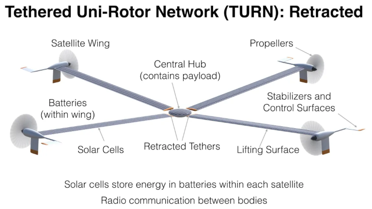
Vehicle Layout: The TURN system has a central hub which stores the vehicle payload. Several high tensile, small diameter cable tethers radiate outwards from the central hub. At the end of each tether, a satellite body is attached at the outboard position. Each satellite contains all the components typically found on an aircraft system, including: an airfoil lifting section, small propeller for propulsion, several control surfaces, and a fuselage containing batteries, hardware, and sensors. Each satellite resembles a flying-wing aircraft, which provides all the lift, propulsion and control for the TURN system. The propeller is mounted on the leading edge of the wing, located near the outer wingtip. Immediately behind the prop, stabilizers and control surfaces are located directly in the prop wash. The concept was named Tethered Uni-Rotor Network because a network of aircraft systems are tethered together to form a much larger singular rotor system.
Hover Operation: During flight, the vehicle operates in a perpetual state of rotation. Each of the satellite bodies drive the rotation of the system with their respective propulsion systems, which have an optimum twist and pitch designed for the rotation rate. This propulsion technique is opposite that of a conventional helicopter rotor, where a torque is applied to the central shaft, which requires a counter-torque to prevent the helicopter body from spinning in the reverse direction. Since this is a tip driven system, there is no torque transmitted back to the central hub. Because the system is spinning, centrifugal forces keep the tethers taught and mitigate bending moments commonly present within thin wing sections. As the satellite bodies move through the air, lift is generated on each of the winged airfoil sections, which is enough to counteract the weight of the satellite, and a distributed portion of the weight of the central hub.
Flight Operation: Individual satellites are controlled through their propeller and control surfaces, and the central hub is controlled by coordinating the tether forces imparted from the satellite vehicles. Two types of translation are considered, vertical and horizontal, which have a parallel in helicopter terminology as “collective” and “cyclic” commands. Each type of translation has two associated control modes which can be implemented through different control inputs.
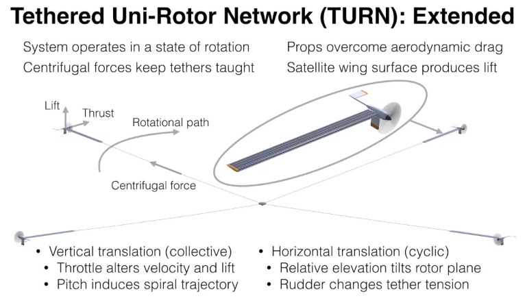
Vertical translation uses “collective” commands where each satellite adjusts its settings in unison. Adjusting throttle increases or decreases the velocity of the satellite, and thus the angular rate of the TURN system. This changes the amount of airflow over the wing, which increases or decreases the total amount of lift generated, and causes the vehicle to ascend or descend. Alternatively, adjusting the pitch of each satellite through the elevator control surface, causes each satellite to nose up or down, thus the entire system will climb or fall as each satellite moves through a spiral trajectory.
Attaining persistent flight requires a paradigm shift in the vehicle design. By taking the best features of both glider and helicopter design methodologies, a new concept vehicle is able to incorporate each of their benefits while minimizing their detriments.